
Our project to build a Dual PIII-S 1.4Ghz system on the Asus P2B-DS
mainboard ran into a serious problem when it was found the Upgradeware
Slot-T adapters we were planning to use did not work in CPU slot 2 on
our mainboard - the system ran perfectly with a single PIII-S and Slot-T
in CPU slot 1, but would not POST when the CPU and adapter were moved to
slot 2. Upgradeware technical support were unable to resolve the issue,
so we resorted to modifying Asus S370-DL adapters to achieve our goal.
In order to minimise power dissipation at higher clock speeds, Intel
changed the GTL (Gunning Transistor Logic) signal specifications for
Tualatin processors, making them incompatible with S370 mainboards and
slot adapters designed for previous generation S370 processors. The new
specification, named AGTL, reduces the signal voltage (Vtt) to 1.25v
from the previous 1.5v used by AGTL+ processors. In order to prevent
processor damage, Intel defined a previously grounded pin (AN3) as
DYN_OE on the Tualatin processors. If the DYN_OE signal is low, the
processor tri-states the VID (Voltage IDentification) signals, shutting
down the voltage regulator - so the system does not boot. Intel
specifies that DYN_OE should be connected to Vtt via a 1K ohm pullup
resistor on Tualatin platforms, however simply disconnecting it is
sufficient. Intel also re-defined a number of other signals on the
Tualatin processor, two of which must be modified to before the
processors will POST on S370-DL adapters - VttPWRGD (AK4), and RESET2#
(AJ3). These modifications are described here.
The modifications allow Tualatin processors to run on AGTL+
mainboards like the P2B-DS, however they simply bypass the protections
Intel designed in to the Tualatin processors to protect them from AGTL+
signal levels - they do not address the signal incompatibility issue.
The absolute maximum overshoot voltage for AGTL is specified at 1.78v,
0.53 volts above nominal Vtt of 1.25v. The corresponding figure for
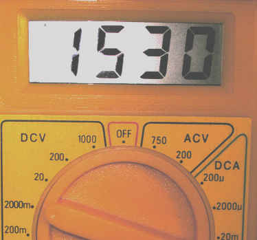
AGTL+ is 2.3v, 0.8v above nominal Vtt of 1.5v. When you run a Tualatin
processor on a BX board, you are trusting it to control overshoots to
no more than 0.28v above nominal Vtt of 1.5v - or in our case 0.25v
above a measured 1.53v. Intel's Tualatin specifications state
"Undershoot and overshoot specifications become more critical as the
process technology for microprocessors shrinks due to thinner gate
oxide. Violating these undershoot and overshoot limits will degrade the
life expectancy of the processor". We do not have access to the
equipment required to measure overshoot voltages on the P2B-DS, however
headroom of 0.25v is a very small margin given the original board
designer was engineering to the 0.8v AGTL+ specification.
 |
 |
In theory, on a Slot 1 system, the 1.5v AGTL+ signals could be
clamped to 1.25v AGTL levels on the slot adapter. Both the Slot-T and
Asus S370-DL adapters have Texas Instruments SN74TVC16222A 22-bit
voltage clamp chips to protect the processor from excessive voltages on
the CMOS signals, which are specified as 2.5v on Slot 1 processors and
1.5v on S370 processors. However, there are nearly 140 AGTL signals in
all - fitting another 7 voltage clamp chips on the adapter would be
quite a challenge!
While clamping signals to AGTL levels on the slot adapter would
protect the CPU from AGTL+ level inputs, it would also cause the CPU to
generate AGTL level outputs - but the mainboard is still running at
AGTL+ signal levels, and would probably mis-interpret logic levels from
the CPU resulting in an unstable system. We suspect this is why the
Slot-T adapter does not adjust the GTL signal levels.
The solution we propose is a compromise - run both the CPU and the
mainboard GTL signals halfway between AGTL and AGTL+ levels, i.e.
1.375v. Actually, Intel's datasheets specify a minimum Vtt of 1.365v for
AGTL+, and a maximum Vtt of 1.3625v for AGTL - so ideally we should set
Vtt to 1.36375v, splitting the difference and minimising the
out-of-specification conditions on both the mainboard and processor.
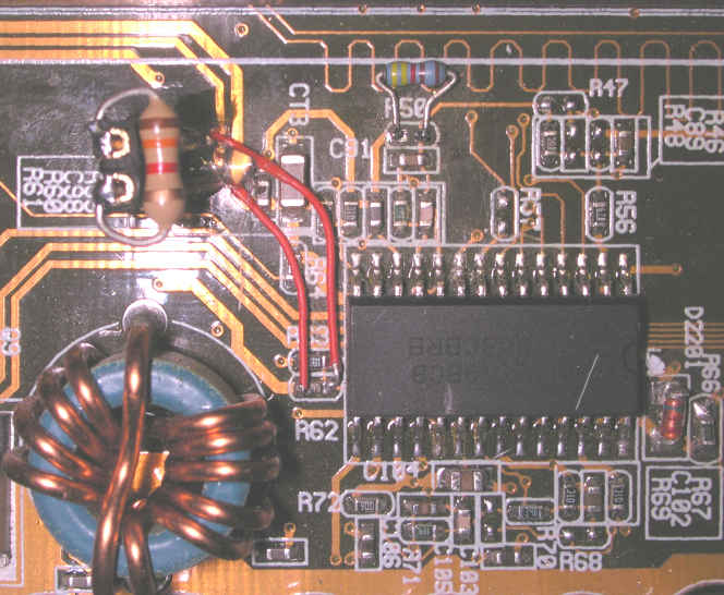
On the Asus P2B-DS, Vtt is generated by the HIP6019BCB voltage
regulator, and it's output voltage is resistor programmable. The Vtt
programming resistors on the P2B-DS are R62 (1.96K ohms) and R63 (10K
ohms). Using the formula in the HIP6019BCB datasheet, we calculate that
Vtt can be lowered to the desired voltage by changing R62 from 1.96K
ohms to 780 ohms. However, we would like this modification to be easily
reversed - just in case it doesn't work, or in case we want to run
non-Tualatin processors on the board in the future. The required 780 ohm
value for R62 can be achieved by placing a 1.3K ohm resistor in
parrallel with the existing resistor, and if we install the new resistor
on a jumper, the modification is easily reversed.
P2B-DS Vtt Modification |
||
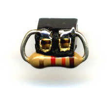 The 1.3K ohm resistor is mounted on an ATX power switch connector, trimmed down so it will not interfere with CPU insertion. A 2-pin header is mounted in a vacant area close to the VRM chip using hot-melt glue, and connected in parrallel with R62. This image also shows the Vio modification (R50) described here. |
 |
|
Vtt - Before
|
Vtt - After
|
 |
 |
The modified P2B-DS successfully ran memtest86 for 48 hours without error at 140Mhz FSB - this appears to be the upper FSB limit for stability on the P2B-DS.
Last updated May 4th, 2003 by p2b@sympatico.ca