The Asus P2B-DS is one of the most stable dual processor Slot 1
motherboards ever produced. It is getting rather long in the tooth these
days (mine was purchased October 19, 1998), but can still provide impressive
performance when paired with more recent Intel processors.
Asus has continued to provide BIOS updates for the P2B-DS, allowing it to support processors which did not exist when the board was designed. BIOS version 1013 ( here ) supports Coppermine processors, while the 1014 beta 3 BIOS ( here ) supports Tutalin processors. The BIOS updates theoretically provide quite a range of PIII and Celeron processor upgrade options for the P2B-DS, however there are other issues to consider.
There are five voltage identification pins (named VID[0-4]) on the Slot
1 connector. These pins are used to support automatic selection of power
supply voltages. These pins are not signals, but are either an open circuit
(logic 1) or a short circuit to ground (logic 0) on the processor. The
combination of opens and shorts defines the voltage required by the processor
core. The power supply must supply the voltage that is requested or disable
itself. The table below shows the VID[0-4] logic states for 1.7v (Pentium
III 1Ghz/100Mhz Slot 1) and 1.8v (minimum available on P2B-DS rev 1.05
and lower).
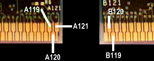
| Voltage | VID0 (Pin B120) | VID1 (Pin A120) | VID2 (Pin A119) | VID3 (Pin B119) | VID4 (Pin A121) |
| 1.7 | 1 | 1 | 1 | 0 | 0 |
| 1.8 | 1 | 0 | 1 | 0 | 0 |
If we can change VID1 from a '1' (open circuit) to a '0', (short circuit to ground), the processor will appear to be requesting 1.8v. This might sound like a task requiring some delicate work with a soldering iron, however there is a better way. VID4, Pin A121, is a '0' and is adjacent to VID1, Pin A120, which we need to change to a '0'.
If we look closely at the Slot 1 connectors on the motherboard, there is a tiny gold contact for each pin on the processor. The contacts are spring loaded, and are forced outward when the processor is inserted into the slot. The upper ends of the contacts are visible in the small rectangular holes on the top of the Slot 1 connector, and move back and forth in these holes as the processor is inserted and removed. If we insert a small U-shaped piece of wire into the rectangular holes corresponding to pins A120 and A121, the gold contacts will be forced against the wire when the processor is inserted, thus connecting A120 to A121 and changing the processor voltage request from 1.7v to 1.8v
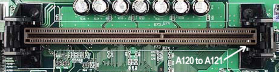
A120 and A121 are located as shown above on the Slot 1 connector
U-Shaped Wire
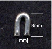 The
U-shaped wire used to connect pins A120 and A121 should be about 3mm tall
and 1 mm wide. It also needs to be just the right diameter. I don't have
a micrometer to measure the diameter but I used the thickest wire I could
find which would fit into the rectangular hole in the top of the Slot 1
connector easily. Use tweezers to drop the wire into the holes. Put wires
in both Slot 1 connectors.
The
U-shaped wire used to connect pins A120 and A121 should be about 3mm tall
and 1 mm wide. It also needs to be just the right diameter. I don't have
a micrometer to measure the diameter but I used the thickest wire I could
find which would fit into the rectangular hole in the top of the Slot 1
connector easily. Use tweezers to drop the wire into the holes. Put wires
in both Slot 1 connectors.
Now insert your processors and connect the fan cables to the headers
on the motherboard. I recommend setting the FSB jumpers for 100Mhz initially,
although my system is perfectly stable with the FSB at 112Mhz. The CPU
multiplier jumpers do not need to be set as the multiplier is locked at
10x on the Pentium III 1Ghz/100Mhz Slot 1 processor.
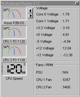
Processor Voltage Check
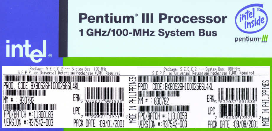
I used S-spec SL4KL retail boxed processors with attached heatsink
and fan for this upgrade.
Last updated October 5th, 2002 by P2B